AUTO · Group Project · 2026 S1
QBot AutonomousNavigation System
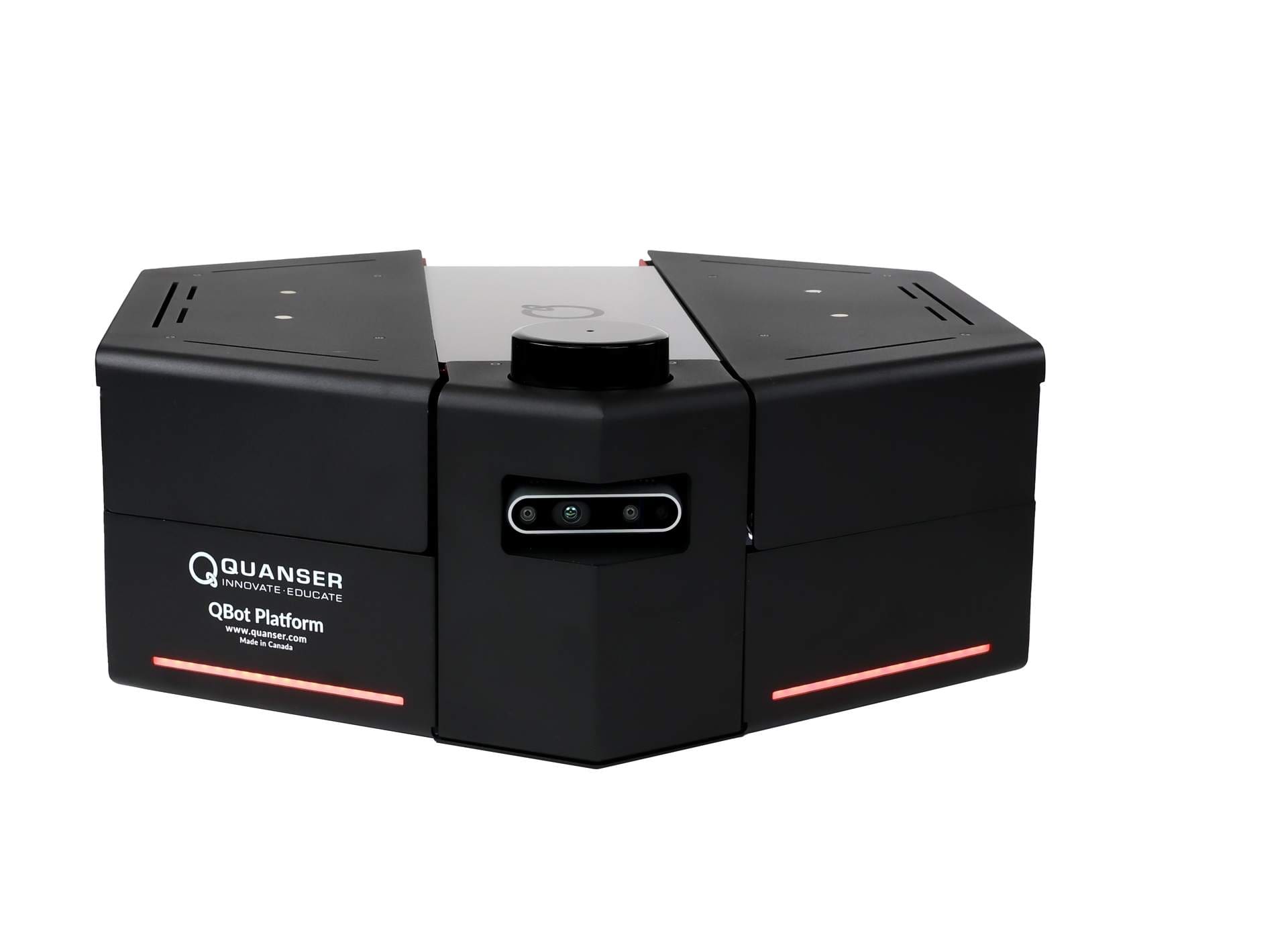
A single Simulink behaviour-arbitration model running on the Quanser QBot Platform. It follows a line, reads traffic signals, avoids obstacles, builds a live occupancy map, and stops at a coloured target — autonomously, on real hardware.
01The Task
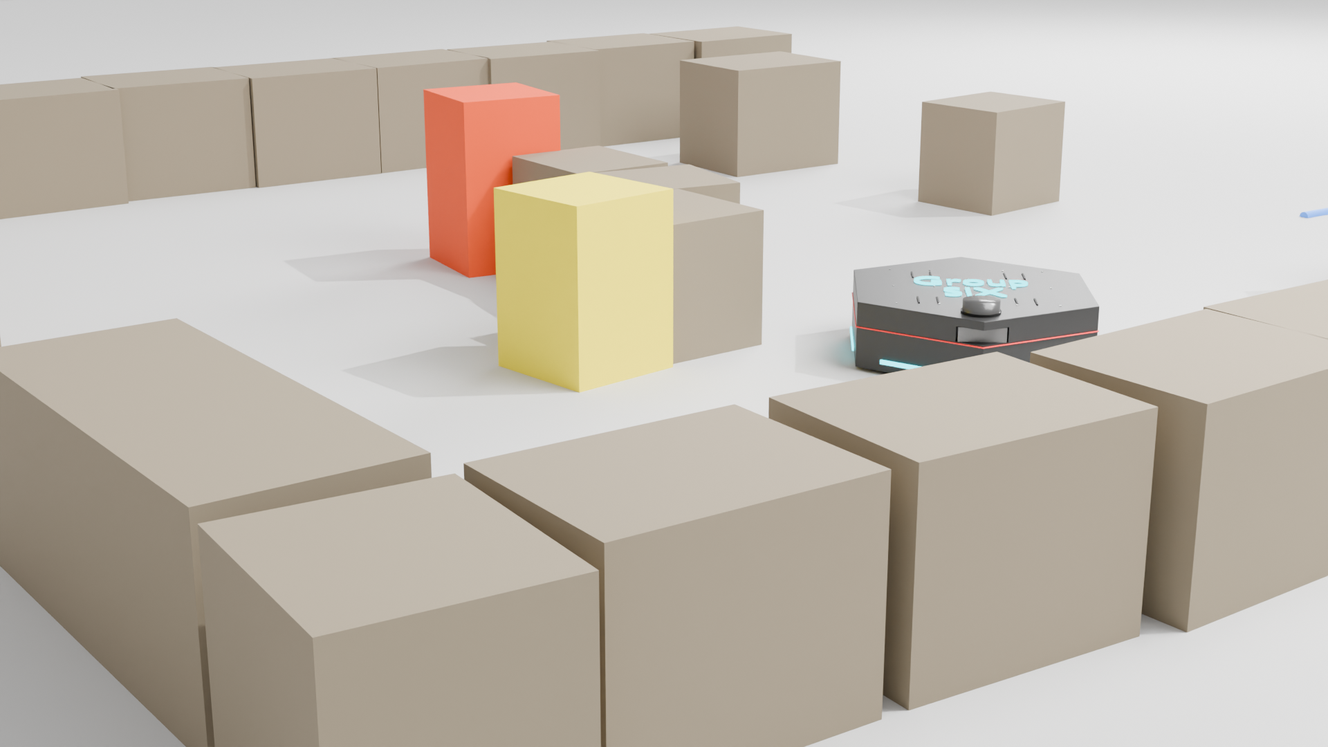
The demo course requires sequential autonomous operation through five distinct phases — from initial line detection through to target acquisition — within a hard 3-minute run cap. Course layout varies between runs.
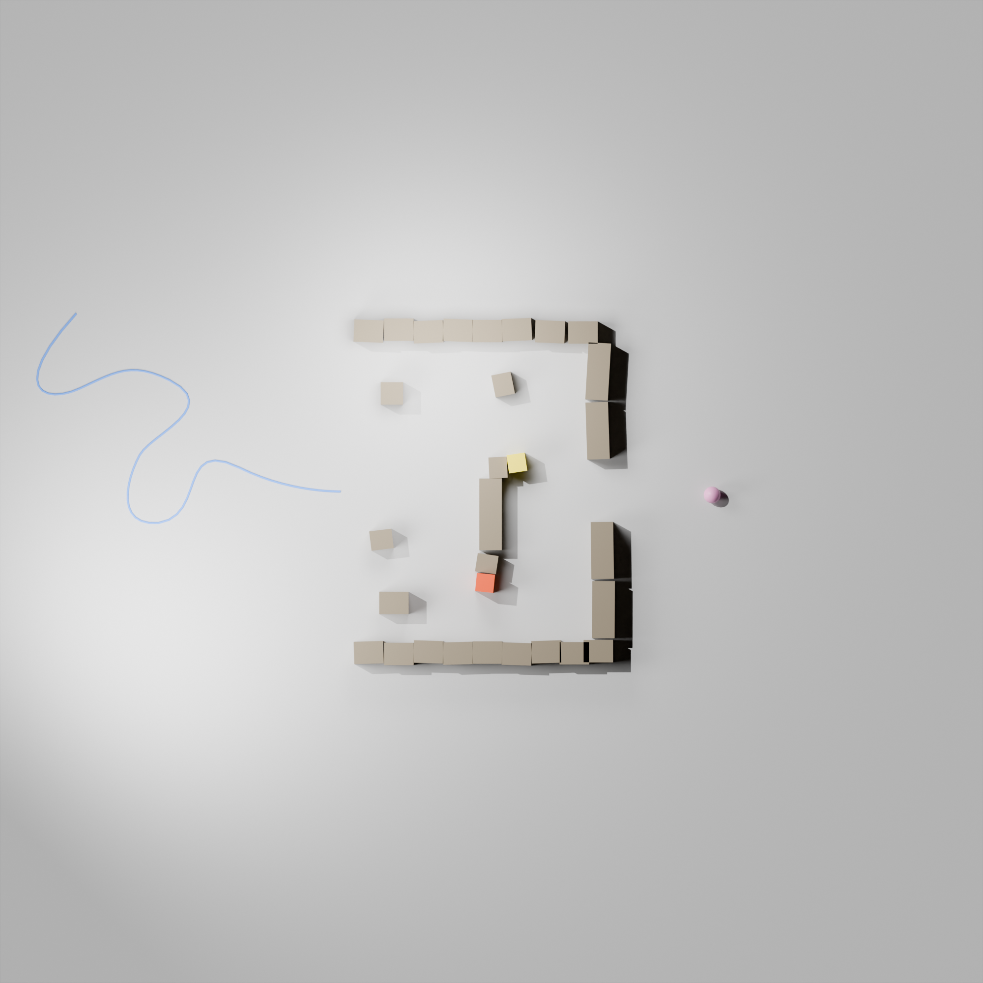
Demo course — top-down view
Guided tour — labelled course zones from line entry to pink target
Course layout varies between runs — obstacles, signals, and target position change
Blue Line Follow
Detect the blue floor strip with the downward camera and follow it onto the course using proportional centroid control.
Build a Map
Fuse RealSense depth point clouds into a persistent 501×501 uint8 occupancy grid as the robot navigates.
Traffic Compliance
Detect red (stop) and yellow (slow) traffic signals with the forward RGB camera and respond with the correct motion command.
Obstacle Avoidance
Detect and avoid obstacles using depth imagery — close-range only, splitting the point cloud left/right and steering away from the nearer side.
Target Approach & Stop
Detect the pink target, approach it proportionally, and stop precisely when target area exceeds 1500 px².
02System Architecture
The complete system is one Simulink model running on the QBot. Every control tick, each behaviour module produces a wheel-velocity vector and a status flag. The arbiter selects exactly one winner and drives the motors — no behaviour holds the motors directly.
Intel RealSense D435 + LIDAR
Forward RGB + depth — traffic, target, obstacles, mapping
Drive base & encoders
Differential drive — wheel encoders feed odometry
Sensors
Behaviour Modules
Arbiter → Motors
S2 == 2 (pink goal reached) sits above all flags — it fires a hard stop before any other behaviour can respond.
Top-level signal flow of the Simulink model — sensors → behaviour modules → arbiter → motor commands, every control tick.
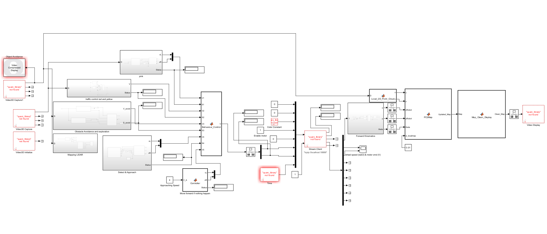
Top-level Simulink model — as implemented on the QBot
Priority-based arbitration is deterministic and transparent — exactly one behaviour wins every tick with no ambiguous transitions. Easier to debug and tune than a state machine with explicit transition guards.
Motor commands run at the QBot step size. Perception, mapping, and the arbiter run at 10× slower. Rate Transitions bridge the boundary — fast enough for smooth control, slow enough for vision processing.
LIDAR data is logged to workspace via To Workspace blocks but not used for navigation. Deliberate choice: the RealSense depth gives forward-facing obstacle data sufficient for the course, and fusing LIDAR mid-semester would have introduced more integration risk than gain.
03Perception
Perception is how the QBot turns raw camera and depth frames into the five decisions it has to make on the course. Four of the five behaviours share one colour pipeline; the depth camera runs a parallel path that builds the map and watches for obstacles. The subsections below follow the order the robot actually uses them.
Blue-line, target and traffic detection all run the same three stages. Only the threshold and the action at the end differ.
- 1SegmentThreshold the frame into a binary mask of the target colour
- 2MeasureCompute the mask area A and its horizontal centroid xc
- 3ActCompare xc to the image centre → proportional wheel command; use A for distance / goal logic
Standard RGB is sensitive to lighting — a well-lit card and a shadowed card of the same colour give different R,G,B values. Chromaticity divides each channel by the total intensity, leaving only the colour ratio. The result is near-invariant to illumination, which mattered when the course lighting changed between calibration and demo day.
total = R + G + B + ε

r = R / total
g = G / total
b = B / total
Environment Mapping
The course layout is unknown and changes between runs, so the robot builds its own map as it drives. Each depth frame becomes a local point cloud, is transformed into the world frame using the odometry pose, then blended into a single persistent occupancy grid. A persistent map variable means the grid is never reset between time steps — it accumulates across the whole run.
Each new scan only nudges the grid: occupied detections raise a cell toward 255, free-space detections slowly clear it back toward 0. Low blend weight keeps a single noisy frame from corrupting the map.
Too small and the full course won't fit on the grid; covers 20 × 20 m here.
Too fine and the model gets heavy — it can slow the real-time run or crash the QBot.
Too high → noisy map; too low → the map updates too slowly to be useful. Tune when the map looks noisy, too small, or runs slow.
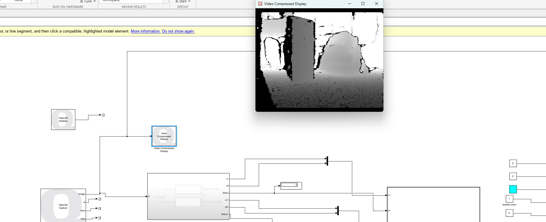
Depth camera → 501×501 occupancy grid — good run at cruise speed
grid(u, v) = (1 - w) × grid(u, v)
            + w × new_obs

w = 0.01  (blend weight)
Low w prevents a single noisy frame corrupting the grid; each occupied detection increments steadily while free-space detections slowly clear cells.
- 1RealSense depth frameRaw 16-bit depth at 30 fps
- 2Reproject to 3DEach pixel → local (X, Y, Z) point using camera intrinsics
- 3Transform to world frameRotate and translate by current odometry pose (x, y, θ)
- 4Project to grid cellworld_X / 0.04 + 251, world_Y / 0.04 + 251 → integer (u, v)
- 5Blend into gridApply the update rule with w = 0.01; clamp to [0, 255]
Each occupied cell is thickened by a 5 × 5 px neighbourhood before the grid is used. At 4 cm/px the robot body is ~4.5 px wide, so the padding lets any path planner treat the robot as a point while keeping clearance around real obstacles.
Compressed video display was used instead of full video, and unnecessary scopes/displays were stripped, so the mapping load doesn't starve the control loop.
Blue Line Following
The robot enters the course by following a blue floor line with its downward camera. The frame is segmented for blue pixels; from that mask the model takes the blue area A and the line centroid xc, then steers proportionally to keep the line centred.
Raw brightness, not chromaticity — the blue line is distinct enough in the brightness channel that normalising adds nothing.
- 01Line near image centre → both wheels forward
- 02Line to the left of centre → turn left
- 03Line to the right of centre → turn right
- 04Line area drops below threshold → BlueLock + last_turn memory recover the line
Minimum blue area to confirm the line is visible. Too high → thinks the line is lost too often; too low → noise gets treated as the line.
Area used to decide the line has ended. Too high → leaves the line early; too low → keeps searching for blue after it ends.
Suppresses tiny centroid errors. Increase if the robot wiggles; reduce if it misses sharp turns.
Correction strength. Increase if it turns too slowly; reduce if it oscillates.
Forward speed — high enough to finish in time, low enough not to overshoot corners or stall the motors.
Downward camera — raw frame, intensity channel [80, 180]
A BlueLock flag and last_turn memory hold the robot's intent through intersections and momentary line loss, so a single dropped frame doesn't hand control to another behaviour.
Target Detection & Approach
Once the pink target is detected, the robot steers toward its centroid exactly like line following — left of centre turn left, right of centre turn right, centred move forward. The target area doubles as a distance estimate: as the robot closes in, the pink area grows.
Pink target isolated by chromaticity so the threshold survives the lighting change between calibration and demo.
- 01Pink detected → steer proportionally toward its centroid
- 02Pink area grows as the robot approaches
- 03Area exceeds Agoal → status becomes 2 (goal reached)
- 04Status 2 → hard stop, highest priority in the arbiter
Stop threshold (~0.5 m standoff). Too low → stops too late / too close; too high → stops too early. Tune during target-stopping tests; requirement is to stop within 1 m.
Minimum area for a confident detection — below this the centroid is unreliable.
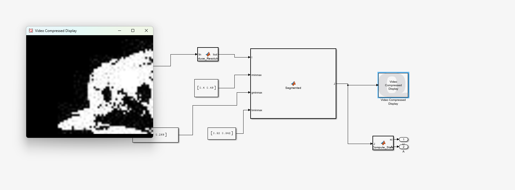
Forward camera — raw frame → chromaticity mask r ∈ [0.40, 0.49]
When the target straddles the image centre, left/right oscillation can occur. A 0.3 s hold on the last steering command stops the robot flipping direction every tick.
Traffic Signal Recognition
The forward RGB camera detects red and yellow signals by chromaticity. The response is priority-based: red means stop, yellow means slow down and proceed with caution — yellow never brings the robot to a full halt because it represents caution, not a stop.
Two chromaticity bands on the same forward camera distinguish a stop signal from a slow signal.
- 01Red detected → stop and hold until the signal clears
- 02Yellow detected → reduce speed, keep moving carefully
- 03Neither → continue with the active navigation behaviour
Too low → reacts to noise; too high → misses the signal. Tune under the actual demo lighting.
Minimum coloured area before a signal is accepted — filters out small false detections.
Red / yellow chromaticity threshold — stop or slow
Obstacle Avoidance
The final design uses close-range avoidance only. The point cloud is split into a left and a right half and the controller takes the minimum distance on each side. Whichever side has the nearer obstacle inside the close threshold, the robot turns away from it.
- 01Split the point cloud into left and right halves
- 02Take the minimum distance on each side
- 03Obstacle close on the left → turn right
- 04Obstacle close on the right → turn left
Distance that triggers avoidance. Too high → turns too early and oscillates; too low → may not avoid in time. Tune when it reacts too early or nearly clips an obstacle.
How long the robot commits to one turn direction before a flip is allowed. Too short → still flickers left↔right; too long → keeps turning after the path is clear.
Close-range avoidance — point cloud split left / right
Far-range avoidance was tested but cut — on a tight course it reacts too early, causing unnecessary turning, hesitation and getting wedged between obstacles. Kept as a system-improvement talking point for the report (see 4.4).
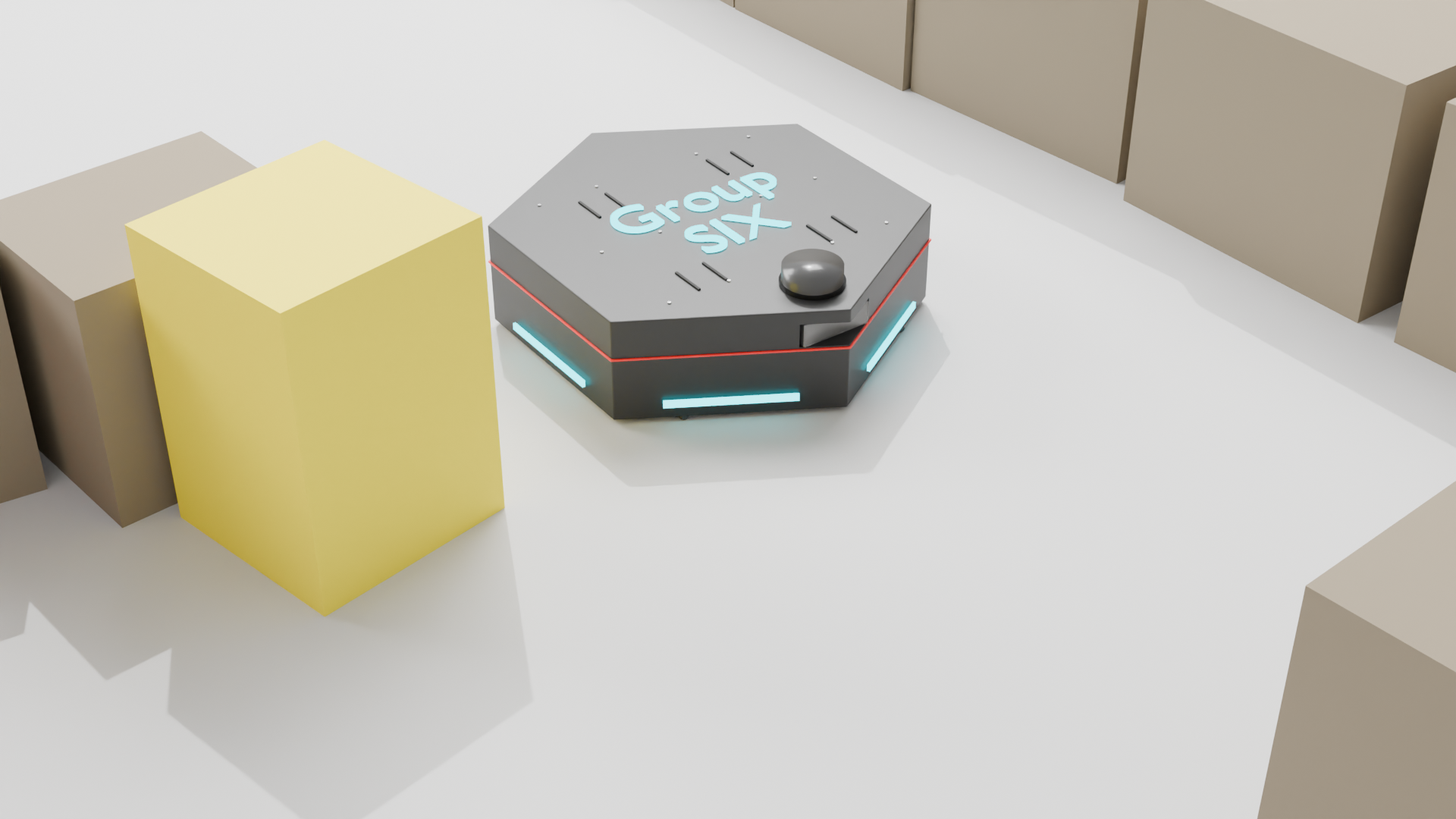
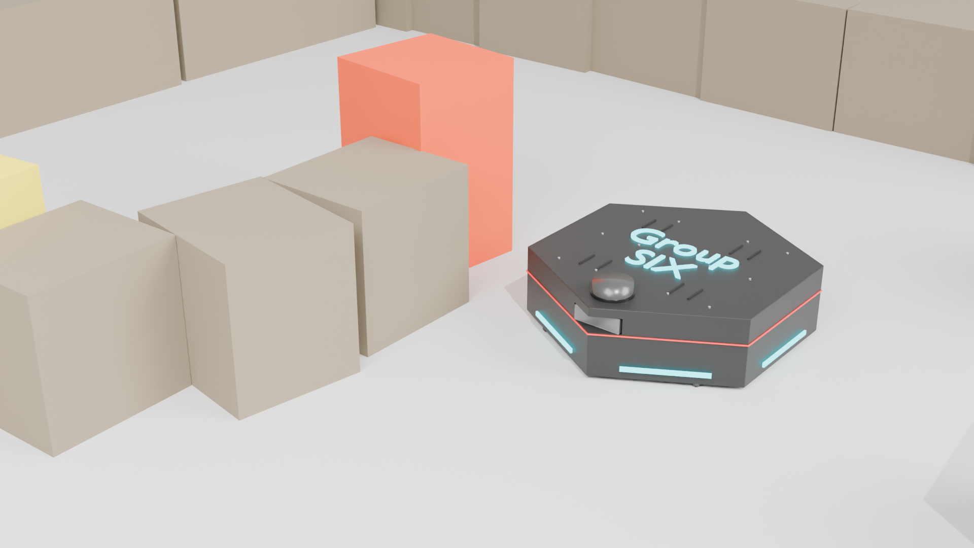
Group SIX · QBot Platform on course
04Behaviour Arbitration
Every tick, the arbiter receives nine inputs — five velocity vectors, four status flags. Six lines of MATLAB select one winner. Priority is fixed: safety first, task second, nominal cruise as fallback.
Obstacle section — close-range steer-away
The point cloud is split into left and right halves and the controller takes the nearest return on each side. If an obstacle falls inside th on one side, the robot steers away from it. Far-range avoidance was removed — on a tight course it reacts too early.
The blue line follower uses a BlueLock flag and last_turn memory to handle intersections and momentary line loss. Once locked onto the line, it stays committed until task completion.
Blue line follow (priority 4) sits above obstacle avoidance (priority 5). Once safety/task triggers clear, the robot immediately resumes line tracking rather than entering avoidance — keeping it on course. Obstacle avoidance still fires when S3 is true and no line is detected, so cornered situations are still handled.
05Parameters
These are not defaults. Each value was taken from the Quanser hardware specification or tuned through iterative lab testing. The rationale column records what we tried first.
| Parameter | Value | Unit | Description | Category |
|---|---|---|---|---|
| r_wheel | 0.04445 | m | Wheel radius — encoder pulse → arc length. Quanser QBot Platform spec, verified by square-path test. | Platform |
| L_wheel | 0.3928 | m | Wheel base — arc → heading change in RL2Centre differential drive model. | Platform |
| v_cruise | 4 | rad/s | Default cruise speed (V5). Balance of run time vs odometry accuracy — 6 rad/s increased mapping artefacts noticeably. | Control |
| w_localmap | 0.01 | — | Map update weight. Low weight prevents one noisy frame corrupting the grid. 0.2 caused severe artefacts in W12 lab. | Mapping |
| wall_pad | 5×5 | px | Neighbourhood thickening on each occupied cell. Robot is ~4.5 px wide at 4 cm/px — 5×5 ensures planner clearance. | Mapping |
| map_size | 501×501 | px | Occupancy grid dimensions. Covers 20×20 m at 4 cm/px resolution. | Mapping |
| th | 0.5 | m | Close obstacle threshold. Point cloud split L/R, robot turns away from the nearer side. Too high → turns too early/oscillates; too low → may not avoid in time. Far avoidance removed for the tight course. | Behaviour |
| turn_time | 0.3 | s | StopFlips hold. Commits to one turn direction before a left↔right flip is allowed. Used on both obstacle avoidance and pink approach. Too short → still flickers; too long → keeps turning when clear. | Behaviour |
| A_goal_pink | 1500 | px² | Pink target area stop threshold. ~0.5 m standoff at typical target size. 800 → too far; 2000 → too close. | Colour |
| A_min_pink | 50 | px² | Minimum pink area for confident detection. Below this, centroid is unreliable. | Colour |
| A_min_blue | 570 | px² | Blue line minimum area before line-loss recovery. 300 triggered recovery too often on faded floor markings. | Colour |
| blue_deadzone | ±5 | px | Centroid deadzone before proportional correction activates. ±5 px ≈ 3° heading error. ±2 caused snaking. | Colour |
| r_pink | [0.40–0.49] | — | Pink chromaticity r-channel range. | Colour |
| r_red | [0.78–0.95] | — | Red (stop signal) chromaticity r-channel range. | Colour |
| r_yellow | [0.47–0.60] | — | Yellow (slow signal) chromaticity r-channel range. | Colour |
| blue_intensity | [80–180] | — | Blue line raw intensity threshold (not chromaticity). Downward camera channel. | Colour |
16 of 16 parameters shown
06Results & Improvements
Results will be updated after the Week 14 demo run. Task scorecard, timing, and map screenshots are placeholders pending the live evaluation.
Task Scorecard
| Task | Metric | Result | Status |
|---|---|---|---|
| Blue Line Follow | Line acquired + followed | TBD | TBD |
| Occupancy Mapping | Grid populated, no artefacts | TBD | TBD |
| Traffic Compliance | Stop on red, slow on yellow | TBD | TBD |
| Obstacle Avoidance | No contact with obstacles | TBD | TBD |
| Target Approach & Stop | Stop ≤ 0.5 m from pink | TBD | TBD |
Timing Breakdown
Demo day — real run footage
QBot Platform as-built — front
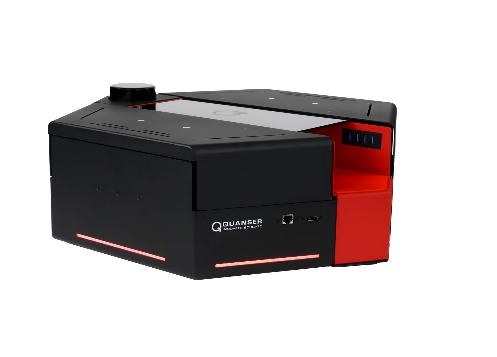
QBot Platform as-built — rear
A map update weight of 0.01 sounds tiny but accumulates reliably over multiple passes — starting at 0.2 was our biggest early mistake.
The StopFlips hysteresis was not in the original design. One lab run revealed left-right oscillation so severe the robot barely moved. 0.3 s fixed it immediately.
LIDAR is already wired — we just don't fuse it. Every future team should fuse it from day one for full 360° awareness.
Chromaticity is genuinely robust to lighting. We tested under three different lab lighting conditions and the same thresholds worked each time.
Far-range obstacle avoidance was tested and removed — on a tight course it steers too early and the robot hesitates or wedges between obstacles. Close-only avoidance with a StopFlips hold proved far more reliable.